How do I...? |
This page is designed to answer some of the most common "How do I...?" customer questions.
|
|
How do I connect my PC to my robot? |
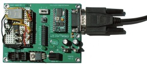
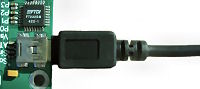
Connecting your robot to your PC is very easy. Simply connect the serial cable from your PC's serial or USB port to the serial port on the Board of Education. The images below shows a serial BOE and USB BOE.
|
USB to PC Connections |
| Download and install the lastest FTDI driver for your USB PSC or BOE. |
| 1. Download the FTDI driver |
| 2. Run the installer |
| 3. Connect your PC |
 |
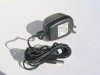 |
Power the BOE by connecting a standard 9V battery to the BOE's 9V battery clips. The BOE also has a 2.1mm x 5.5mm barrel connector that accepts a standard wall-wart 6-9V 500mA power supply. Basic STAMP FAQs |
|
|
How do I program the robot? |
| 1. Start the BASIC Stamp editor. Download the free BASIC Stamp editor form Parallax Inc. |
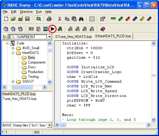 |
2. Open the program related to your CrustCrawler product in the BASIC Stamp editor.
3. Click the Run button in the BASIC Stamp editor's tool bar (red circle above).
All CrustCrawler robots come with pre-written code to accommodate beginning to advanced users. For the beginner we supply all the code necessary to get you up and running. If you can follow instructions and are familiar with Windows programs you'll have no problems with our products.
For the intermediate to advanced coders we supply all the P-Basic component code. You can mix and match or create your own custom applications. |
The servos don't move after I download a program!
How do I get this thing working? |
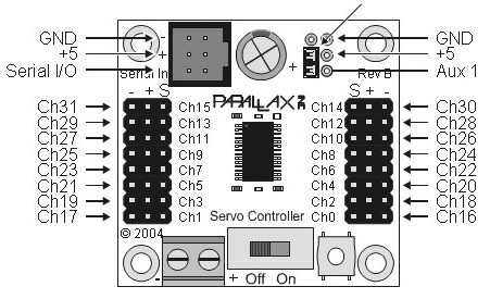
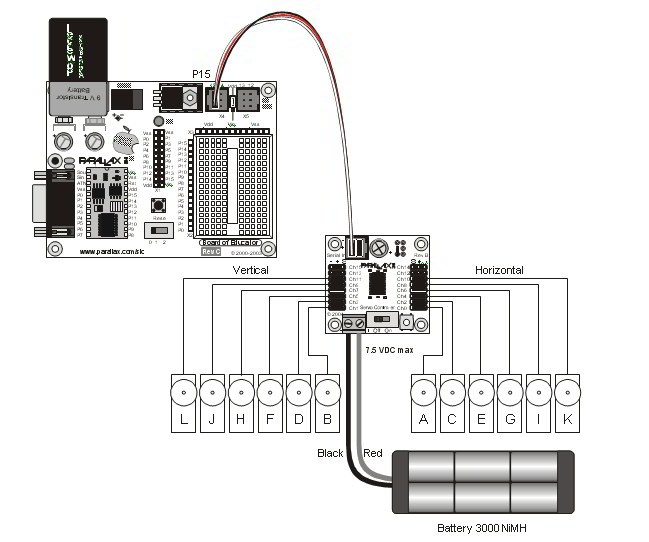
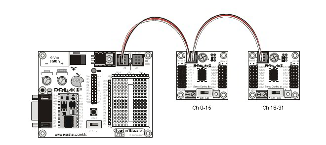
First, check the PSC jumper. If you are using ONE PSC then remove the jumper! Adding the jumper allows the PSC to talk to channels 16 to 31. Please read the PSC manual for more information on networking PSCs (or see schematic below). |
| Next check your connections! Connection issues are very common so don't panic.
CrustCrawler provides two programs to help you troubleshoot connection problems. |
| 1) Ping the PSC to test your BOE/STAMP to PSC connection. |
| 2) Run the Channel Tester to test your PSC to servo connections. |
|
Ping the PSC |
Run Ping the PSC. The debug terminal pops up and displays the PSC firmware version (see the image below). If the debug terminal displays "Finding PSC" multiple times (see second image) check your connections. One end of the red white & black cable is connected to X4 port - Pin 15 on the BOE and the other end is connected to the PSC. (see the BOE/PSC Schematic diagram below).
If you are using the GaitPic (Nomad) you must connect the the X4 port (Pin 15 on the BOE) to the PSC.
Note: If both the PSC's green and red LEDs are ON, you have one end of the red white & black serial cable reversed. |
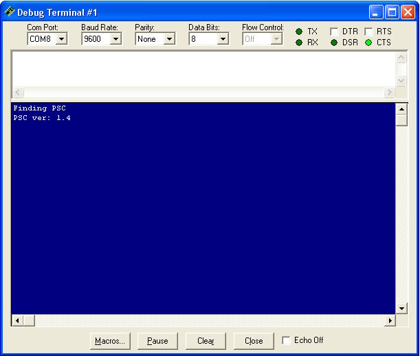 |
| Debug Terminal returned PSC firware version. |
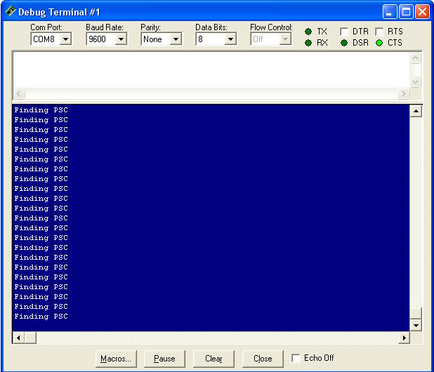 |
| Check your connections! |
Channel Tester |
Once you have verified that PSC and STAMP are communicating, test your PSC to servo connections with the Channel Tester.
1) Remove ALL the servo connection except channel 0 (use tape to label your servo wires). <- Yes, you have to do this step!
2) Verify that the polarity is correct, ground (black) is connected to the outside of the PSC.
3) Check the PSC jumper! (On = channels 16-31 Off = channels 0-15)
4) Run the Channel Tester code.
You should see the servo attached to channel zero move back and forth. (sample code below)
Note: If even one servo connection is reversed none of the servos will function. |
' {$STAMP BS2p}
' {$PBASIC 2.5}

'---- [Programming Notes] ------------------------------------------------

'-----[ I/O Definitions ]-------------------------------------------------
PSC             PIN     15              ' PSC module

#SELECT $STAMP
  #CASE BS2SX, BS2P
    N2400        CON     1021+$8000
  #CASE BS2PX
    N2400        CON     1646+$8000
  #CASE #ELSE
    N2400        CON     396+$8000
#ENDSELECT


'-------------------------------------------------------------------------

servoAddr       VAR     Byte            ' Servo addresses
ramp            VAR     Byte            ' Ramp used in SEROUT
position        VAR     Word

'-------------------------------------------------------------------------


ramp = $F             ' Ramp (speed)
servoAddr = 0         ' Channel 0

Main:
  position = 500      ' Position
  GOSUB Write_Joint   ' Send position command
  PAUSE 3000          ' Pause 3 seconds
  position = 1000     ' Position
  GOSUB Write_Joint   ' Send position command
  PAUSE 3000          ' Pause 3 seconds
GOTO Main             ' Loop

' Write to the PSC
Write_Joint:
  SEROUT PSC,N2400,["!SC",ServoAddr, Ramp,position.LOWBYTE, position.HIGHBYTE, CR]
RETURN
|
To test channel 1 find and edit the line of code below.
servoAddr = 1 ' Channel 0
Run the code. |
|
How do I network the BOE and PSC |
|
PSC Schematics |
Serial PSC |
USB PSC |
 |
 |
|
|
BOE/PSC Connections |
 |
|
PSC Network |
 |
| |